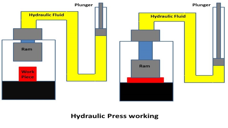
A hydraulic press diagram explains how keek the fluid pressure is transferred from the piston to the rod by using two cylinders, one for the hydraulic fluid and one for the air. As shown in the diagram, the pressure exerted on the piston on one cylinder acts on the other at 90 degrees. The larger the cylinder, the larger the force (F2)), and the smaller weworld the cylinder, the less force (F1).
As the name implies, a hydraulic press uses the Pascal’s principle to apply pressure on a workpiece. It uses this principle to transform large skillpage metal objects into thin sheets. It’s also used to crush scraps and old vehicles. The sales staff and manufacturers of hydraulic presses work with their clients to find the best machine for the project. Depending on the type of application, a hydraulic press can range from a tabletop essembly model for laboratories to a large, industrial-sized machine that applies hundreds of tons of pressure.
Hydraulic presses are designed to use an operator. The operator feeds the stock through the hydraulic press, positions the stock on the bottom filestube die, and activates the press cycle. Once the press cycle is complete, the operator can safely remove the finished product. There are many different kinds of hydraulic presses, but a basic hydraulic press diagram explains how each type works. The differences between single and double-column presses are listed below.

